Shared Mobile AR Without Depth Sensors from Monocular Point Maps
Abstract
Depth-aware augmented reality on phones needs dense geometry of the surrounding room. iPhones and iPads without LiDAR expose only sparse feature points and detected planes, and ARKit often takes tens of seconds to report the first wall. We describe a scan-free pipeline for these devices. A point-map network (MoGe-2) predicts metric geometry from each camera frame, the remaining depth shift is recovered from the camera intrinsics, and each frame's scale is aligned to views already in the map. A persistent voxel map with visibility-based expiry answers occlusion and collision queries. Co-located devices share one coordinate frame by solving yaw and floor-plane translation from sightings of each other. We evaluate the deployed system on 309 device-sessions from 19 device models without LiDAR, with 179 device-sessions from LiDAR phones in the same deployment as a reference population. A first dense depth map was recorded within 10 s in 80% of sessions, while ARKit had reported a wall plane by then in 25%. The median session scale was 0.98 against ARKit's wall planes and 1.00 against its camera translation. Scale changed by a median of 9% between nearby frames, against 0.4% with LiDAR, and depth points spread three times as widely around walls. In multi-device sessions, 69% of devices without LiDAR reached a converged shared frame, against 84% of LiDAR phones. The main remaining error is scale that changes from frame to frame.
1. Introduction
Occlusion, collision and placement of virtual content in augmented reality (AR) all need dense geometry of the room. LiDAR iPhones obtain it from ARKit scene depth [1], and supported Android phones obtain a depth image from ARCore [2, 3]. LiDAR is available only on Pro iPhones and some iPads, and iPhones without it have no general rear-camera depth API. ARKit gives them tracked feature points and planes, and both depend on texture and camera motion. If the user starts interacting at once, the application cannot reliably tell, for the first seconds to minutes, whether a virtual object is behind a wall.
We call a system scan-free if it provides dense geometry without first asking the user to move the camera around the room, and shared if several co-located devices place content in one coordinate frame without exchanging or overlapping visual maps. This paper asks whether monocular depth on devices without LiDAR supports both, and measures where it falls short.
The pipeline runs MoGe-2 [4], a network that predicts a metric point map, on every processed frame. The one unknown left by the point map, a shift along the optical axis, is solved from the camera intrinsics that ARKit reports. Frames are fused into a persistent voxel map, and each new frame's scale is partly corrected toward overlapping views already in the map. Surfaces expire after a fixed time and are invalidated when a newer ray passes through them. For shared use, gravity and the floor reduce the alignment between two devices to a yaw angle and a horizontal translation, which a server solves from the devices' sightings of each other.
The system was deployed in an iOS AR application, and we evaluate it on telemetry from that deployment. The telemetry contains the depth grids, camera poses and intrinsics, ARKit planes and the shared-frame solutions, but no images and no ground-truth depth. We therefore compare the depth with two references that ARKit derives from its visual-inertial metric scale on every device, its wall planes and its camera translation, and use LiDAR phones in the same deployment as a reference population. A small controlled study against LiDAR supplements these proxies.
The contributions are as follows.
- A scan-free monocular mapping pipeline for devices without depth sensors, combining point-map prediction with intrinsics-based shift recovery, frame-to-map scale alignment and visibility-based surface expiry.
- A shared-frame method that registers co-located devices from mutual sightings, with no shared visual map. We report how often and how fast it converges in the field. Its accuracy was not measured against an external reference.
- A field evaluation on 488 device-sessions from 32 device models, with separate analyses of 417 devices in multi-device sessions, using ARKit geometry and LiDAR phones as references.
2. Related Work
2.1 Depth on phones
Valentin et al. [3] showed that depth from camera motion can drive occlusion and physics on phones, and their method underlies the ARCore Depth API [2]. DepthLab [5] organized the uses of such depth into point, surface and dense queries, and our map answers queries of these kinds. These systems need parallax, so a stationary or rotating camera yields little depth. Dense mobile reconstruction from a single camera, as in MobileFusion [6], also requires the user to move the camera through the scene. LiDAR removes the problem on the devices that have it [1].
2.2 Monocular geometry and its scale
Monocular networks differ in what they leave unresolved (Table 1). Relative-depth models such as ZipDepth [7] predict inverse depth up to an affine transform, which must be fitted to metric references on every frame. Metric depth models such as Depth Anything V2 Metric [8], Metric3D [9], UniDepth [10] and Depth Pro [11] predict metres directly, which makes their scale depend on how well they infer the focal length. MoGe [12] predicts an affine-invariant point map and recovers its shift from the image geometry, and MoGe-2 [4] adds a metric scale. With known intrinsics only the shift remains to be solved. Absolute scale remains a learned prior.
| Model family | Output | Unknown per frame | Resolved by |
|---|---|---|---|
| Relative depth (ZipDepth) | inverse depth up to | , | fit to metric points |
| Metric depth (Depth Anything V2 Metric) | depth in metres | none nominally | learned prior |
| Metric point map (MoGe-2) | points and scale | shift | camera intrinsics |
Per-frame predictions are not consistent over time. Video-depth methods enforce consistency by optimizing over a whole sequence [13], which is too slow for a phone. We instead fuse each frame into a map online (Section 3.2).
2.3 Dense mapping
Volumetric fusion [14] and voxel maps with ray-cast free-space clearing [15] are standard for depth sensors. Dense monocular SLAM such as CNN-SLAM [16] and DROID-SLAM [17] estimates pose and depth jointly but is too heavy for older phones. We take poses from ARKit's visual-inertial odometry [18] and fuse predicted depth into a coarse voxel map.
2.4 Shared AR
ARKit collaborative sessions [19] and ARCore Cloud Anchors [20] align devices by matching visual features of the room, which requires them to have observed the same surfaces. Collaborative SLAM [21] does the same with shared keyframes. Multi-robot systems instead localize robots from relative observations of each other [22]. We use this second approach, with users observing each other.
3. Method
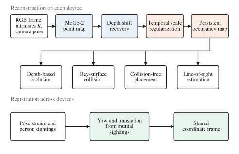
Figure 1 shows the pipeline. Each device builds its own map from its own camera. Only camera poses and observations of other users are sent to the server.
3.1 Metric depth per frame
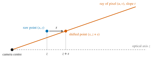
MoGe-2 (ViT-S, 35M parameters) maps a RGB frame to a point map at and a scale . The point map is correct up to a shift along the optical axis. With normalized image coordinates and from ARKit's intrinsics for that frame, the shifted points must lie on their pixel rays (Figure 2). We solve
with ten Gauss–Newton steps over an pixel lattice, following MoGe's solver [12] with the field of view fixed. Depth is then
Equation (1) fixes the shift but not the absolute scale, which still comes from .
The deployed model uses 8-bit palettized weights (29.7 MB). Its output is resampled to a depth grid, and depth between 0.35 m and 24.9 m is kept. At initialization the model is timed on the CPU and on the Neural Engine, and the Neural Engine is used only if it is at least 15% faster and its output agrees with the CPU output to within 3%.
3.2 Scale across frames
A persistent map accumulates every frame, so a frame whose scale is off by a few percent adds a second copy of a wall behind or in front of the first. Before a frame is fused, its points are reprojected into retained views within 1.5 m, and the median ratio between the frame's depth and those views' depth is computed. The frame is rescaled by
with first divided by its mean over the frame's recent history, so the rule changes relative scale only. Absolute scale therefore stays with the model, apart from two corrections. Pixels that fall within about 18 cm of ARKit's floor height are snapped to the floor. A fit to ARKit feature points can rescale a frame when enough points agree, and in test recordings on an iPhone 11 Pro it rarely did. A stronger setting of Equation (3), and , made free-space placement worse in offline replays of recorded sessions, and was not used.
3.3 Persistent map
The map is a voxel grid with 20 cm cells. Each cell stores whether it is occupied, free or unknown, the source of the observation and the time it was observed. A surface seen once expires after 30 s and one seen repeatedly after 120 s. If a newer ray ends behind an occupied cell, the cell is marked as seen through. It then no longer occludes virtual objects or blocks line-of-sight queries, but still blocks moving virtual objects until it expires. A cell observed only once is cleared outright when a later ray passes through it. The map answers four queries, which are occlusion of virtual objects, ray–surface collision, placement in free space and line of sight. Occlusion is resolved per object at the map's 20 cm resolution and not per pixel.
3.4 Shared frame
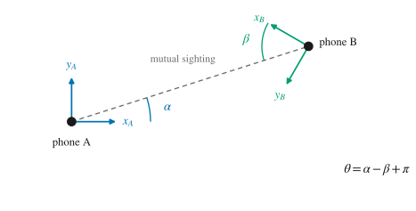
ARKit aligns each device's vertical axis with gravity. If each device also measures its height above the floor, the transform between two devices reduces to a yaw and a horizontal translation . When device sees device 's user at bearing and sees 's user at bearing at the same time, the two lines of sight are antiparallel (Figure 3), so
A bearing needs only the image position of the observed user and the camera intrinsics, so the yaw does not depend on depth. Translation also needs the distance to the observed user, which a device reads from its depth map where it can. A sighting without a reliable distance constrains only the yaw. A server pairs each sighting with the observed device's pose at that time, fits for every device with a robust estimator, and marks a device converged once its predicted position uncertainty falls below a fixed threshold.
4. Data and Measures
4.1 Deployment telemetry
Telemetry was collected only from users who declared themselves adults. Collection is on by default and can be disabled in the settings. The records used here are depth grids with their camera pose and intrinsics, ARKit planes, ARKit feature-point counts, frame timing and the server's shared-frame solutions. They contain no images, audio or names, identifiers are pseudonymous per session, and we report aggregates only.
We used sessions recorded from 19 to 30 October 2026, while the pipeline described here was deployed, that lasted at least 60 s (90 s for single-device sessions). The fleet sets keep device-sessions that uploaded at least five depth grids, 309 of 496 without LiDAR and 179 of 246 with LiDAR. The shared set keeps every iPhone or iPad in a multi-device session that received a shared-frame solution, whether or not it uploaded depth, so it overlaps the fleet sets only in part. The unit of analysis is the device-session, one device in one session. A user who opened the application several times contributes several device-sessions, and identifiers do not allow clustering by user. Bootstrap intervals resample whole sessions. Table 2 summarizes the data.
| Set | Devices | Reference | Size |
|---|---|---|---|
| Fleet without LiDAR | 16 iPhone and 3 iPad models, MoGe-2 on device | ARKit planes and camera translation | 309 device-sessions, 12.9 h, 23,363 depth grids |
| LiDAR fleet | 13 models with LiDAR | the same | 179 device-sessions, 7.6 h, 44,559 depth grids |
| Shared | 2 to 6 devices per session | solver state | 193 sessions, 417 iPhones and iPads |
| Controlled, sparse | iPhone 11 Pro | ARKit feature points | 36 frames, 3 sessions |
| Controlled, dense | iPhone 15 Pro | LiDAR depth | 4 views, 160,511 pixels |
| Controlled, live | iPhone 15 Pro, MoGe-2 on device | LiDAR depth | 245 frames, 4 sessions |
Users chose their own rooms and motion, so the fleet sets are not a controlled sample. Telemetry samples depth less often than the model runs, so a device-session contributes a median of 49 depth grids without LiDAR and 197 with it. LiDAR phones are newer Pro devices, and their users may differ in rooms and behaviour as well as in sensors, so the LiDAR fleet is a reference population, not a matched control.
4.2 Measures
All fleet measures use the recorded depth grid, which is the deployed output after Equation (3) and the floor snap. In every scale measure, rays pointing more than 0.15 rad (8.6°) below the horizon are excluded, which removes floor pixels that the snap could make agree with ARKit by construction. Shares "within 10%" mean .
Time to geometry. The time from session start to the first recorded depth grid and to the first vertical plane reported by ARKit. Because every session lasted at least 60 s, the shares at 10, 30 and 60 s are plain proportions. Sessions that end before an event are censored in the curves beyond 60 s (Kaplan–Meier).
Scale against wall planes. For up to 60 depth grids per session, pixels whose rays hit the polygon of an ARKit vertical plane known at that time, between 0.3 m and 5 m, give a ratio of predicted depth to ray–plane depth. Planes must have an area of at least 0.3 m². We discard pixels whose ratio is off by more than a factor of 2 (14% of hits on both device classes, mostly furniture in front of walls), take the median per frame and plane, then the median over the session.
Scale against camera translation. ARKit's camera translation is metric. For pairs of depth grids within 4 s whose camera centres are at least 0.3 m apart, we scale the first grid by , move its points into the second camera with the ARKit poses, and compare them with the second grid scaled by . Under pure rotation every fits equally well. With translation only the correct scale makes the two views agree. We search over a factor of , take the value that minimizes the median absolute log-ratio, and report , the ratio of predicted to metric depth, as the median over up to 60 pairs.
Frame-to-frame scale change. For consecutive grids at most 2.5 s apart whose camera centres moved less than 10 cm, the median ratio of reprojected to observed depth, reported as in percent. With a small baseline a constant scale error contributes little, so this measures scale that changes over time, plus pose and sensor error. We exclude pairs in which the same model output was recorded twice (), which was 46% of such pairs without LiDAR and 2% with it.
Wall thickness. For each ARKit wall plane, the perpendicular offsets of all depth points that hit it within 5 m, pooled over the session. We report the interquartile range of the offsets, as the median over planes with at least 200 points from at least three frames. It grows with scale error, scale change and the error of the plane itself.
Shared frame. Whether and when each device's state became converged, the solver's reported uncertainty while converged, and the change in yaw after convergence.
4.3 Controlled study
On four views recorded with an iPhone 15 Pro, we compared three models on the same frames against LiDAR (0.35 m to 5 m). MoGe-2 ran offline at full precision with its own field-of-view estimate, which differs from the deployed configuration. Depth Anything V2 Metric Small ran at , the input that fitted the time budget of older phones, and at . ZipDepth was fitted to half of the LiDAR pixels and scored on the other half, which gives it an advantage that no deployed system has. On 36 frames from three iPhone 11 Pro sessions, we also scored the models against ARKit feature points. In a third test, an iPhone 15 Pro ran the deployed MoGe-2 model on its Neural Engine every 1.5 s during use, and the raw output, before Equation (3), was scored against that frame's LiDAR depth.
5. Results
5.1 Geometry without scanning
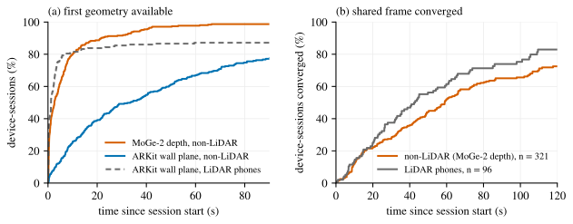
On devices without LiDAR, the first depth grid was recorded after a median of 2.6 s (interquartile range 0.4 to 7.9 s), and by 10 s 80% of device-sessions had one (Figure 4a). This is an upper bound on when the map had geometry, because telemetry samples depth less often than the model runs. On the same devices ARKit had reported a vertical plane in 25% of sessions by 10 s, 49% by 30 s and 67% by 60 s, and in 52 of the 309 sessions it reported none. On LiDAR phones 82% of sessions had a wall plane within 10 s. Where both events occurred, the plane came a median of 14 s after the first depth grid (257 sessions). ARKit tracked a median of 35 feature points per frame and reported 1.5 vertical planes per minute, against 16.4 on LiDAR phones.
5.2 Metric scale
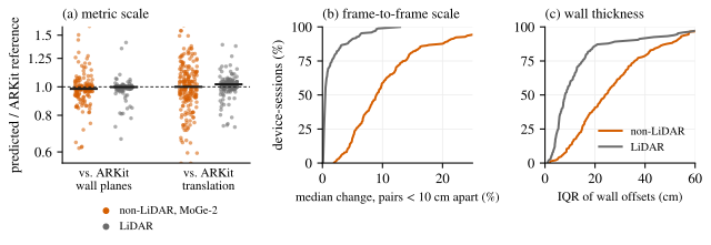
Table 3 and Figure 5a give the scale of the deployed depth against the two ARKit references. Against wall planes, the median session ratio was 0.984 (95% interval 0.976 to 0.994) over 155 device-sessions, and 70% of sessions were within 10%. Against camera translation, the median was 1.00 (0.98 to 1.03) over 208 device-sessions, and 47% were within 10%. LiDAR phones gave 0.998 and 1.02. On LiDAR phones ARKit's planes are themselves informed by LiDAR, so their small spread is a lower bound on the noise of the measures, and the reference is noisier on devices without LiDAR. Session medians by chip generation ranged from 0.96 to 1.01 against wall planes and from 0.96 to 1.10 against translation, with no trend from A13 to A19.
The two estimates agree in the population median but not per session (Spearman correlation 0.06, 95% interval to 0.24, over 124 sessions with both). Per-session values are therefore dominated by measurement noise, and the spread in Table 3 likely overstates how much the true scale varied between sessions. Both references share ARKit's visual-inertial scale, and the deployed output includes the occasional fit to ARKit feature points, so agreement with ARKit is partly by construction. The raw model, measured against LiDAR in Section 5.6, read 16% short.
| Measure | Without LiDAR, MoGe-2 | LiDAR phones |
|---|---|---|
| Scale against wall planes | 0.984 [0.938 to 1.024], n = 155 | 0.998 [0.986 to 1.001], n = 149 |
| Sessions within 10% / 20% | 70% / 86% | 91% / 95% |
| Scale against camera translation | 1.00 [0.91 to 1.12], n = 208 | 1.02 [0.98 to 1.04], n = 156 |
| Sessions within 10% / 20% | 47% / 68% | 82% / 93% |
| Frame-to-frame scale change | 9.0% [5.7 to 13.7], n = 234 | 0.44% [0.27 to 1.54], n = 173 |
| Wall thickness (IQR of offsets) | 24 cm [15 to 36], n = 145 | 8.1 cm [5.3 to 15.1], n = 148 |
5.3 Consistency over time
Scale changed between nearby frames even after Equation (3). The median frame-to-frame change was 9.0% per session (95% interval 8.2% to 9.8%), against 0.44% for LiDAR (Figure 5b). Of 5,526 pairs without LiDAR, 45% differed by more than 10% and 17% by more than 30%, against 8% above 10% for LiDAR. The interquartile range of depth points around ARKit wall planes was 24 cm, three times the 8.1 cm of LiDAR phones (Figure 5c). This is consistent with walls being widened by scale that changes between the frames that observe them, although error in ARKit's planes also contributes.
5.4 Shared frame
Of 321 devices without LiDAR in 193 multi-device sessions, 220 (69%) reached the converged state, against 81 of 96 LiDAR phones (84%). Among devices that converged, the median time was 37 s without LiDAR and 35 s with it. By 60 s, 52% and 62% had converged, respectively (Figure 4b). Within the 85 sessions that mixed both device classes, 73% of devices without LiDAR and 84% of LiDAR phones converged. While converged, the solver reported a median lateral uncertainty of 0.36 m for both classes. After convergence the yaw still moved by a median of 5.7° and 6.9°, respectively. A 6° change moves a point 8 m away by about 0.8 m, more than twice the reported uncertainty, so the solver's uncertainty understates how much the frame still changed.
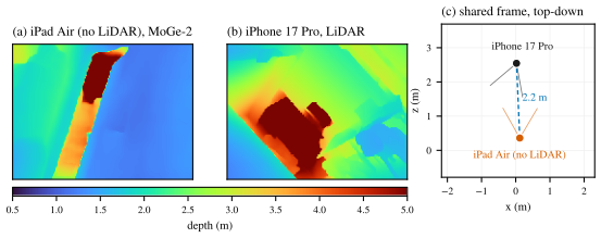
The gap between the classes is consistent with range availability. Without LiDAR, 40% of sightings carried a distance read from the depth map, and 44% carried only a bearing. With LiDAR the shares were 75% and 15%. Sightings with a distance were at a median of 2.7 m and 2.5 m, respectively. These are the solver's own measures. Without an external reference, such as motion capture, they show how often and how quickly the frame converged but not how accurate it was. Figure 6 shows one converged pair.
5.5 Runtime
The 95th percentile of frame time had a median of 17.2 ms on devices without LiDAR and 17.4 ms on LiDAR phones, close to the 16.7 ms of 60 Hz. Across chip generations from A13 to A19 the median ranged from 17.1 to 17.5 ms. We did not measure the same devices with the model disabled or over long sessions, so this shows that frame times matched those of LiDAR phones, not that the model costs nothing. Model latency was measured on two phones. An iPhone 11 Pro (A13) took a median of 306 ms per prediction on its CPU (95th percentile 436 ms, 477 predictions), which the timing test of Section 3.1 chose over the Neural Engine. An iPhone 15 Pro took 34.6 ms with the Neural Engine (245 predictions). On an A13 device the map is therefore updated about three times per second.
5.6 Controlled accuracy
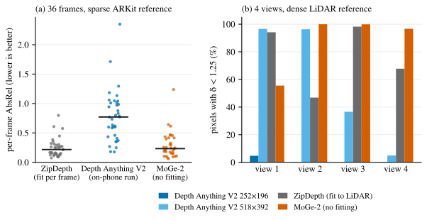
On the four LiDAR views (Table 4, Figure 7b), MoGe-2 placed 97% to 100% of pixels within a factor of 1.25 of LiDAR on three views and 56% on the fourth, without any fitting. Depth Anything V2 at the input placed under 5% of pixels within that bound on every view, and at between 5% and 97%. ZipDepth, fitted to the LiDAR of each view, reached only 47% and 68% on two views, likely because inverting a disparity fit amplifies small errors at far pixels. On the 36 iPhone 11 Pro frames scored against ARKit feature points (Figure 7a), the median per-frame AbsRel was 0.22 for ZipDepth fitted to half of each frame's points, 0.77 for Depth Anything V2 as run on the phone, and 0.23 for MoGe-2. Feature points cover only textured surfaces, which may be why the dense views separate the models more clearly. Four views from one residence cannot establish accuracy in general. On these views, the point-map model was the only one within a factor of 1.25 on most pixels without fitting.
| Model and input | Fitted to LiDAR | Pixels within a factor of 1.25, per view | AbsRel, median over views |
|---|---|---|---|
| Depth Anything V2 Metric Small, | no | 4.7%, 0.2%, 0.0%, 0.2% | 1.28 |
| Depth Anything V2 Metric Small, | no | 97%, 96%, 37%, 5% | 0.20 |
| ZipDepth, affine fit | yes | 94%, 47%, 98%, 68% | 1.15 |
| MoGe-2, full precision | no | 56%, 100%, 100%, 97% | 0.06 |
The raw on-device output on the iPhone 15 Pro was less accurate (Figure 8). Across 245 frames the per-frame AbsRel had a median of 0.20 and the per-frame scale ratio a median of 0.84, with session medians from 0.68 to 0.99. Consecutive frames 1.5 s apart differed in scale by a median of 12%. Replaying a temporal version of Equation (3), which pulls each frame toward the mean of the five before it, reduced that to 7% and changed the session medians by at most 5%.
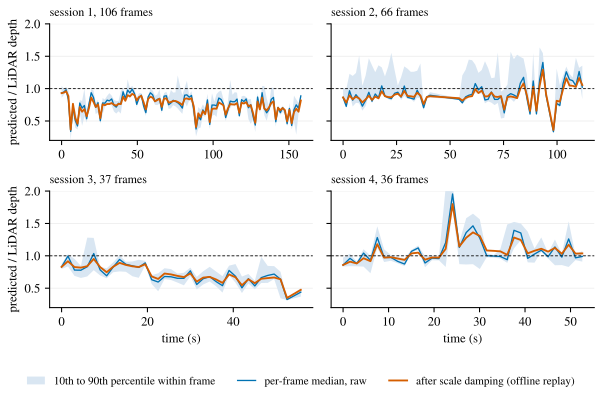
The raw on-device depth was about 16% short (median ratio 0.84), while the deployed depth in the fleet was within 2% of ARKit. The two differ in reference (LiDAR against ARKit geometry), in rooms and devices (one residence and one phone against many), and in processing (raw output against the deployed output after the floor snap and the occasional fit to feature points). These data do not separate the causes. Running the deployed pipeline on LiDAR phones in the field and comparing it with their LiDAR depth would.
6. Discussion and Limitations
Monocular point maps made dense depth available within seconds on devices where ARKit needed tens of seconds to report a wall, or never reported one. Across the fleet, the median scale of the deployed depth was within 2% of ARKit's metric frame. The clearest remaining error is scale that changes between nearby frames, by a median of 9% against 0.4% for LiDAR, which is consistent with depth points spreading three times as widely around walls. Frame-to-frame alignment reduces this change but does not remove it, and it cannot correct a session whose overall scale is wrong, because it keeps the session's own mean. The shared frame converged on 69% of devices without LiDAR and 84% of LiDAR phones, in a similar median time. Fewer sightings without LiDAR carried a depth-based range, which may explain the gap.
The evaluation has the following limits.
- The fleet measures are proxies derived from ARKit, which shares its visual-inertial scale with both scale references, and the deployed output is partly fitted to ARKit. The two scale estimates do not agree per session, so they support statements about the population and not about one session.
- The telemetry stores depth after the deployed corrections, so it cannot separate the raw model from Equation (3) and the floor snap in the field.
- The data cover 12 days, iOS only and the users of one application. Users chose rooms and motion, only sessions of at least 60 s were kept, and one user can contribute several device-sessions. The LiDAR fleet differs from the fleet without LiDAR in devices and users as well as in its sensor.
- Query correctness for occlusion, collision and placement was not evaluated in the field.
- The shared-frame results use the solver's own convergence criterion, and the yaw kept moving after convergence. Accuracy was not measured against an external reference.
- Ground-truth accuracy comes from one residence and one LiDAR phone, and the dense comparison did not use the deployed model configuration.
Sharing also has limits. Mutual sightings need users to face each other, and the floor-based reduction to three degrees of freedom assumes a single floor level.
7. Conclusion
A metric point-map network with intrinsics-based shift recovery gives devices without depth sensors dense depth within seconds and without a scanning phase. In 309 deployed device-sessions on 19 models, the median scale was within 2% of ARKit's, and frame times matched those of LiDAR phones on chips from A13 to A19. In multi-device sessions, 69% of the 321 devices without LiDAR reached a converged shared frame. The main weakness is scale that changes from frame to frame, which widens surfaces in the map. Future work should anchor scale per frame against the map more strongly, measure the deployed output against LiDAR in the field, and measure shared-frame accuracy against an external reference.
Data and Competing Interests
The author develops the application from which the telemetry was collected. The raw telemetry cannot be released. The aggregate tables behind each figure are available from the author on request.
References
- Apple. ARKit. Apple Developer Documentation, developer.apple.com/documentation/arkit.
- Google. Depth API. ARCore Developer Guides, developers.google.com/ar/develop/depth.
- J. Valentin et al. "Depth from motion for smartphone AR." ACM Transactions on Graphics (SIGGRAPH Asia), 37(6), 193, 2018.
- R. Wang et al. "MoGe-2: Accurate monocular geometry with metric scale and sharp details." Advances in Neural Information Processing Systems (NeurIPS), 2025. arXiv:2507.02546.
- R. Du et al. "DepthLab: Real-time 3D interaction with depth maps for mobile augmented reality." ACM Symposium on User Interface Software and Technology (UIST), 2020, pp. 829–843.
- P. Ondrúška, P. Kohli, and S. Izadi. "MobileFusion: Real-time volumetric surface reconstruction and dense tracking on mobile phones." IEEE Transactions on Visualization and Computer Graphics, 21(11), 1251–1258, 2015.
- F. Tosi, L. Bartolomei, M. Poggi, and S. Mattoccia. "ZipDepth: Bringing lightweight zero-shot monocular depth anywhere, on any device." 2026. arXiv:2607.08771.
- L. Yang et al. "Depth Anything V2." Advances in Neural Information Processing Systems (NeurIPS), 2024.
- W. Yin et al. "Metric3D: Towards zero-shot metric 3D prediction from a single image." IEEE/CVF International Conference on Computer Vision (ICCV), 2023, pp. 9043–9053.
- L. Piccinelli et al. "UniDepth: Universal monocular metric depth estimation." IEEE/CVF Conference on Computer Vision and Pattern Recognition (CVPR), 2024.
- A. Bochkovskii et al. "Depth Pro: Sharp monocular metric depth in less than a second." International Conference on Learning Representations (ICLR), 2025. arXiv:2410.02073.
- R. Wang, S. Xu, C. Dai, J. Xiang, Y. Deng, X. Tong, and J. Yang. "MoGe: Unlocking accurate monocular geometry estimation for open-domain images with optimal training supervision." IEEE/CVF Conference on Computer Vision and Pattern Recognition (CVPR), 2025, pp. 5261–5271.
- X. Luo, J.-B. Huang, R. Szeliski, K. Matzen, and J. Kopf. "Consistent video depth estimation." ACM Transactions on Graphics (SIGGRAPH), 39(4), 71, 2020.
- R. A. Newcombe et al. "KinectFusion: Real-time dense surface mapping and tracking." IEEE International Symposium on Mixed and Augmented Reality (ISMAR), 2011, pp. 127–136.
- H. Oleynikova, Z. Taylor, M. Fehr, R. Siegwart, and J. Nieto. "Voxblox: Incremental 3D Euclidean signed distance fields for on-board MAV planning." IEEE/RSJ International Conference on Intelligent Robots and Systems (IROS), 2017.
- K. Tateno, F. Tombari, I. Laina, and N. Navab. "CNN-SLAM: Real-time dense monocular SLAM with learned depth prediction." IEEE/CVF Conference on Computer Vision and Pattern Recognition (CVPR), 2017.
- Z. Teed and J. Deng. "DROID-SLAM: Deep visual SLAM for monocular, stereo, and RGB-D cameras." Advances in Neural Information Processing Systems (NeurIPS), 2021.
- T. Qin, P. Li, and S. Shen. "VINS-Mono: A robust and versatile monocular visual-inertial state estimator." IEEE Transactions on Robotics, 34(4), 1004–1020, 2018.
- Apple. Creating a collaborative session. Apple Developer Documentation, developer.apple.com/documentation/arkit/creating-a-collaborative-session.
- Google. Cloud Anchors allow different users to share AR experiences. ARCore Developer Guides, developers.google.com/ar/develop/cloud-anchors.
- P. Schmuck and M. Chli. "CCM-SLAM: Robust and efficient centralized collaborative monocular simultaneous localization and mapping for robotic teams." Journal of Field Robotics, 36(4), 763–781, 2019.
- A. Franchi, G. Oriolo, and P. Stegagno. "Mutual localization in multi-robot systems using anonymous relative measurements." The International Journal of Robotics Research, 32(11), 1302–1322, 2013.